Having designed some logic gates using relays, I had the foundations of doing simple math with a pure relay circuit. This is where the adder comes into play.
To understand how adders work you really have to start with a brief discussion of base 2 vs base 10 mathematics. Everybody should be familiar with base 10. It is the common mode of mathematics where there are 10 possible numbers (1,2,3,4,5,6,7,8,9,0) that are used in a particular way to represent all numbers. However, base 2 is the number system that most computer use.
Understanding BASE 2 (BINARY)
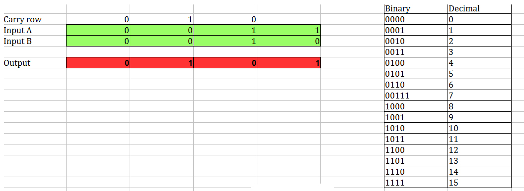
Base 2, also known as binary, uses only 2 numbers (1 & 0). This makes it possible to represent a full numerical system using the electrical concept of charge (1) or no charge (0). Meaning that those on or off inputs and outputs into logic gates allow us to build a system that can do calculations. To better understand this for myself, I setup a 4 binary adder in Excel so that I could really see how this math works.

Feel free to download the 4-bit Binary Adder if you want to mess around with it.
In this example screenshot I am adding 3 + 2 (look at the key to the right for a conversion to base 10.) To work with adding binary numbers we start from the right and work our way left, always thinking about SUM and CARRY. Here is my break-down of the step-by-step addition of 3 + 2 in binary:
Starting on the far right column adding Input A + Input B
- 1 + 0 = 1
That makes perfect sense.
Second Column:
- 0 + 1 + 1 = 0
This looks weird of course. But with only two numbers (Base 2) if something is more than 1 then it has to be 0. Meaning that 1 + 1 = 0 (With a CARRY of 1). If you look at the top of the third column the Carry row has a 1. That is the product of our addition in column 2.
Third Column:
- 1 + 0 + 0 = 1
Looks good.
Fourth Column:
- 0 + 0 + 0 = 0
All these columns represent a “bit” in computing, meaning that this adder is a 4-bit adder! Armed with this understanding of the simple SUM & CARRY mechanics of a 4-bit adder it becomes clear (well sorta) how you can make circuits that can add numbers together.
A close examination of the Excel adder should reveal that there are really two kinds of adding going on. The first column (bit) takes only two inputs, while the remaining three rows take 3 inputs. This represents the two different kinds of adders.
The Half Adder Circuit
The half adder is the simple guy. He takes 2 inputs and produces a SUM and a CARRY. This is accomplished with an AND gate and an XOR gate. An XOR (Exclusive OR) is very similar to an OR gate except that the inputs must be different. Check Out the Wikipedia entry on XOR gates for further clarification (and a truth table!).
Truth tables are also very useful for understanding adders. This is a truth table for a Half Adder:
INPUTS OUTPUTS
A B SUM CARRY
0 0 0 0
0 1 1 0
1 0 1 0
1 1 0 1
Looking at this truth table and the far right column in the Excel adder, it should be clear that they do the same thing.
With the understanding of how a Half Adder should work, I designed one using two relays:

By imagining the flow of current, like I did with the relay logic gates, I checked to make sure that this circuit produces the same result as a Half Adder truth table. The CARRY output being the result of an AND gate, while the SUM output is the result of an XOR gate.
The Full Adder Circuit
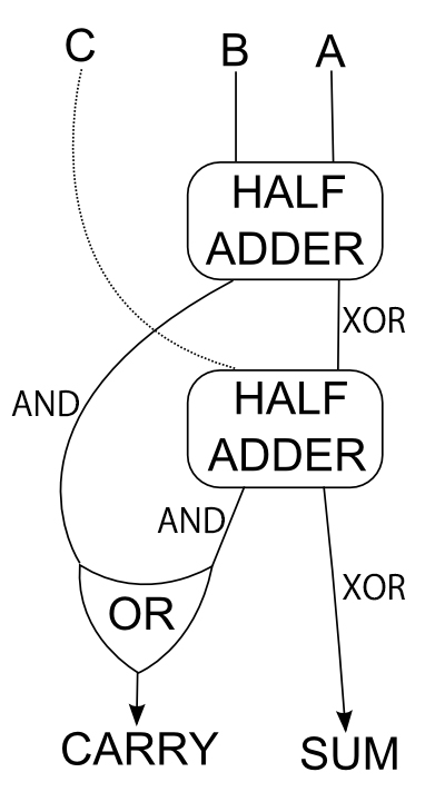
When you start thinking about a Full Adder it becomes obvious about how the Half Adder got its name. The Full Adder is really just 2 half adders put together, plus a little extra bit to deal with the CARRY. I made sure to map this out before trying to piece together the schematic:

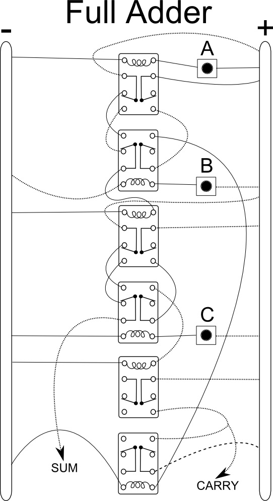
The OR gate in the bottom left is enough to handle the CARRY onto the next full adder. If you start with a HALF ADDER and string together three Full Adders after it, then you have a 4-bit adder! The rest of the work to designing the full adder was just the tedious matter of connecting all the dots:

I encourage you to try and examine the diagram and follow the logic “flow” through the adder to see how it works. The results of this circuit should be the same as a the results of the last three columns in the Excel adder.
Having designed the structures necessary to build a 4-bit adder, I really wanted to build the real deal. Which is exactly what I did next.